

Employee
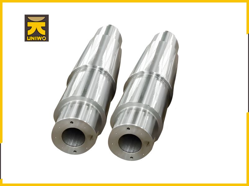
Customized Experience
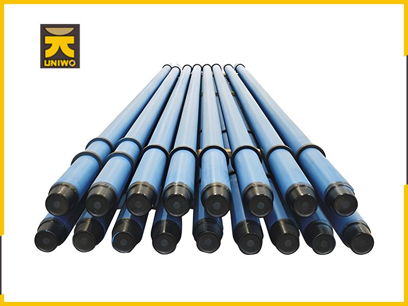
Equipment
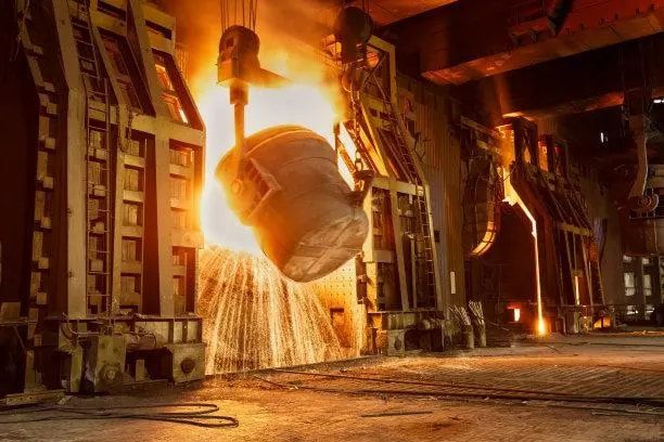
Factory Area
Cutting ForceWhen cutting the front and back of the tool are subjected to normal force and friction, these forces constitute the resultant force F, when turning the outer circle, generally this cutting force F is broken down into three vertical components (Figure 3[cutting force and component force]) : tangential force F - it is perpendicular to the cutting speed direction of the tool base surface, often called the main cutting force; Radial force F -- in the plane parallel to the base surface, perpendicular to the feed direction, also known as thrust; Axial force F -- in the plane parallel to the base plane, parallel to the feed direction, also known as the feed force. Under normal circumstances,F is large,F and F are small, due to the geometric parameters of the tool grinding quality and wear conditions are different and the change of cutting conditions,F,F to F ratio changes in a large range.The actual cutting force in the cutting process can be measured by the dynamometer. There are many kinds of dynamometer, the more commonly used are resistance wire and piezoelectric crystal dynamometer. After calibration, the dynamometer can measure the size of each component force in the cutting process.Cutting HeatWhen cutting metal, the work made by the shear deformation of the chip and the work made by the friction in front of the tool and behind the tool are converted into heat, which is called cutting heat. When the cutting fluid is used, the cutting heat on the tool, workpiece and chips is mainly carried away by the cutting fluid. When the cutting fluid is not used, the cutting heat is mainly taken away or transmitted from the chips, workpieces and tools, of which the heat taken away by the chips is large, and the heat transmitted to the tool is small, but the temperature in front and behind affects the cutting process and the wear of the tool, so it is very necessary to understand the changing law of the cutting temperature.Cutting TemperatureThe temperature of the cutting area is different throughout the cutting process, forming a temperature field of chip and workpiece temperature distribution, this temperature field affects chip deformation, the size of the chip tumor, the quality of the processing surface, processing accuracy and tool wear, but also affects the improvement of cutting speed.Generally speaking, the metal in the cutting zone becomes chips after shear deformation, and then further develops severe friction with the front of the tool, so the high point of the temperature distribution in the temperature field is not at the edge of the positive pressure, but at a distance from the edge in the front. The temperature distribution in the cutting zone must be measured by artificial thermocouple method or infrared temperature measurement method. The temperature measured by the natural thermocouple method is only the average temperature in the cutting zone.Tool WearThe wear during cutting is the comprehensive result of the physical and chemical action caused by cutting heat and mechanical friction. The tool wear is characterized by the wear bands, notches and falling edges on the back of the tool, the crescents on the front, and the oxidation pits and grooves on the back of the tool. When these wear extend to a certain extent, it will cause the tool to fail and cannot be continued. The factors of the gradual wear of the tool usually include abrasive wear, adhesive wear, diffusion wear, oxidation wear, thermal cracking wear and plastic deformation. Under different cutting conditions, especially at different cutting speeds, the tool is subjected to one or more of the above wear mechanisms. For example, at lower cutting speeds, tools are generally damaged by abrasive wear or adhesive wear; At higher speeds, diffusion wear, oxidation wear and plastic deformation are easy to occur.Tool LifeThe cutting time passed before the cutting tool life criterion is called the tool life (once called tool durability), the tool life criterion generally adopts a predetermined value of the tool wear, and can also be used as a criterion for the appearance of a phenomenon, such as vibration intensification, machining surface roughness deterioration, poor chip breaking and falling edge. After reaching the tool life, the tool should be reground, transposed or discarded. The sum of each tool life before the tool is discarded is called the total tool life.In production, the tool life and working hour quota are often determined according to the principle of low production cost or high productivity according to the processing conditions.MachinabilityRefers to the degree of ease of machining parts into qualified products. According to the specific processing objects and requirements, the length of tool life, the quality of the machining surface, the level of metal removal rate, the size of the cutting power and the difficulty of chip breaking can be used as criteria. In production and experimental research, it is often used as an indicator of the machinability of a material, and its meaning is: when the tool life is minutes, the cutting speed allowed to cut the material. The higher it is, the better the process ability, generally 60, 30, 20 or 10 minutes.Machining Surface QualityUsually includes surface roughness work hardening residual stress, surface cracks and metallographic microstructure changes. There are many factors that affect the quality of the machining surface, such as the feed amount of the tool tip arc radius and chip nodulation are the main factors that affect the surface roughness. The blunt edge radius, wear and cutting conditions are the main factors affecting work hardening and residual stress. Therefore, the machining surface quality is often improved by changing the geometry of the tool and selecting reasonable cutting conditions in production.Cutting VibrationDuring the cutting process, there are often types of mechanical vibrations such as free vibration, vibration or self-excited vibration (flutter) between the tool and the workpiece. Free vibration is caused by some sudden impact on the parts of the machine tool, and it will gradually decay. Vibration is caused by the continuous alternating interference force inside or outside the machine tool (such as unbalanced machine tool moving parts, intermittent cutting, etc.), and its impact on the cutting depends on the size and frequency of the interference force. Self-excited vibration is caused by the sudden interference force between the tool and the workpiece (such as hard points encountered in cutting) and the initial vibration, so that the front Angle of the tool, the back Angle and the cutting speed are changed, and the vibration mode coupling is generated, and the energy of the periodic action is obtained from the energy of the steady state action to promote and maintain the vibration. Usually, according to the cutting conditions may produce a variety of primary self-excited vibration, so that the vibration marks left on the machining surface will produce a more common regenerative self-excited vibration. The above vibrations usually affect the surface quality of the tool, reduce the life of the machine tool and the tool, reduce productivity, and cause noise, which is extremely harmful and must be eliminated or reduced.Chip ControlRefers to controlling the shape and length of chips. By controlling the crimp radius and discharge direction of the chips, the chips hit the workpiece or the tool, and the crimp radius of the chips is increased, and the stress in the chips is gradually increased, until the crimp radius of the broken chips can be controlled by changing the thickness of the chips, grinding the chip-rolling groove or the chip-breaking table in front of the tool. The discharge direction is mainly controlled by selecting reasonable main declination Angle and edge inclination Angle. Modern people have been able to use two or three digit coding to indicate the shape of various chips, and it is usually considered that the short arc chip is a reasonable chip shape.Cutting FluidAlso known as cooling lubricant, it is used to reduce friction and reduce cutting temperature during cutting to improve tool life, processing quality and production efficiency. Commonly used cutting fluids include cutting oil, emulsion and chemical cutting fluids.
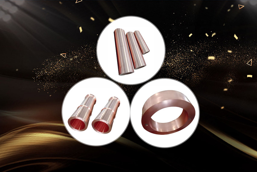
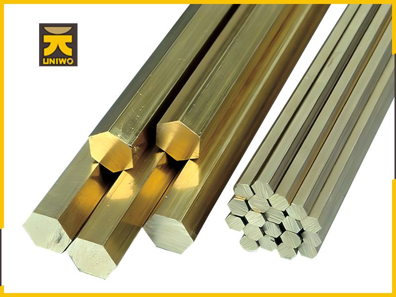
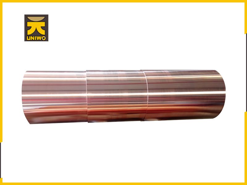
Copper in non-ferrous metals is one of the metal materials used by human beings. Modern non-ferrous metals and their alloys have become indispensable structural and functional materials in machinery manufacturing, construction, electronics industry, aerospace, nuclear energy utilization and other fields.In practical applications, non-ferrous metals are usually divided into five categories:① Light metalDensity is less than 4500 kg/cubic meter (0.53 ~ 4.5g/cm3), such as aluminum, magnesium, potassium, sodium, calcium, strontium, barium, etc.② Heavy metalsDensity greater than 4500 kg/cubic meter (4.5g/cm3), such as copper, nickel, cobalt, lead, zinc, tin, antimony, bismuth, cadmium, mercury, etc.③ Precious metalsThe price is more expensive than common metals, the crust abundance is low, the purification is difficult, and the chemical properties are stable, such as gold, silver and platinum group metals.④ semi-metalProperties between metal and non-metal, such as silicon, selenium, tellurium, arsenic, boron, etc.⑤ Rare metalsIncluding rare light metals, such as lithium, rubidium, cesium, etc.Rare refractory metals, such as titanium, zirconium, molybdenum, tungsten, etc.Rare dispersed metals, such as gallium, indium, germanium, etc.;Rare earth metals, such as scandium, yttrium, lanthanide metals;Radioactive metals such as radium, francium, polonium, and uranium and thorium in the alkene elements.
Address
Luoyang Airport Industrial Cluster, Matun Town, Mengjin District, Luoyang City, Henan Province, China (Middle section of New 310 National Highway)
Telephone:+86 15670317688
Wechat:15670317688
Whatsapp:+86 15670317688
15670317688@163.com
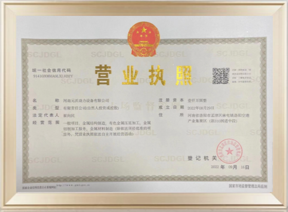
Henan UNIWO Power Equipment Co., Ltd CopyRight ICP:Yu ICP Bei 2023012867-1
Address:Luoyang Airport Industrial Cluster, Matun Town, Mengjin District, Luoyang City, Henan Province, China (Middle section of New 310 National Highway)